

Inertial Measurement Test Request
In the Inertial Measurement Laboratory infrastructure, the necessary performance tests and calibrations are carried out for the Rotometers, Accelerometers and Inertial Measurement Units (IMUs) used in Navigation and Guidance Systems for both military and civilian purposes. Since 1994, in this infrastructure, Inertial Gauges and Inertial Measurement Units used in all SAGE's Guided Munition projects (Precision Guidance Kits, SOM, etc.) have been and are being tested. In addition, this infrastructure has worked with many companies in Turkey within the scope of industrial services.
TS EN ISO 9001:2015 Quality Management System is implemented in the infrastructure. In addition, some of the standards used for Inertial Gauge tests are given below:
- IEEE Std. 528 - 2001: Standard for Inertial Sensor Terminology.
- IEEE Std. 1293 - 1998: Standard Specification Format Guide and Test Procedure for Linear Single-Axis, Nongyroscopic Accelerometers.
- IEEE Std. 836 - 2001: Recommended Practice for Precision Centrifuge Testing of Linear Accelerometers.
- IEEE Std. 952 - 1997 (R2002): IEEE Standard Specification Format Guide and Test Procedure for Single-Axis Interferometric Fiber Optic Gyros.
Accelerometer Tests
With these tests, the technical specifications of linear accelerometers can be verified and the calibration parameters of each accelerometer can be found. The stability of these parameters and their variation with changing temperature can be calculated. These tests are divided into two parts: Allan Variance Tests and Calibration Tests.
Allan Variance Tests
These tests are performed by taking long term (hourly) data from stationary gauges. Different noise-induced errors are calculated from the graph plotted as a result of the process based on the differences of the group means of these meter data. The calculated errors are as follows:
- Quantization Noise
- Speed Random Walk
- Constant Shear Instability
- Long Duration Noise
Allan variance tests can be performed using the index table, three-axis motion simulator, two-axis motion simulator.
Calibration Tests
Each accelerometer undergoes calibration tests separately. Calibration tests are performed by applying high-precision acceleration inputs to the accelerometer using the appropriate index table, centrifuge device, three- or two-axis motion simulator devices. Calibration Tests can be divided into Position Tests and Centrifuge Tests. Position Tests can be performed by using index table, three or two axis motion simulator devices. In Position Tests, gravitational acceleration components in the range of ±1 g are applied to the accelerometer. As a result of these position tests, constant drift, coefficient of proportion and angle drift values are calculated for accelerometers.
With Centrifuge Tests, the coefficient of proportionality and linearity of the coefficient of proportionality under high acceleration values are calculated throughout the accelerometer measurement range. With these calculated coefficients, the calibration matrix of the meters is created. This matrix is input to the AÖB or navigation software. After these tests, calibration tests can be repeated in detail at different temperatures. In this way, the change and repeatability of the parameters depending on the temperature are tested.
Test Specimen Specifications and Delivery Conditions
MEMs (Micro-Electro-Mechanical Systems) or pendulum quartz accelerometers can be used for these tests.
Suitable test setup for accelerometer testing should be selected and configured. This test setup should mainly include sensor mounting fixture, software and electronic equipment required to operate accelerometer and measure its output. After the test setup is complete, test plan is prepared and the results of all measurements are reported.
Basic Devices Used in These Tests and Their Technical Specifications
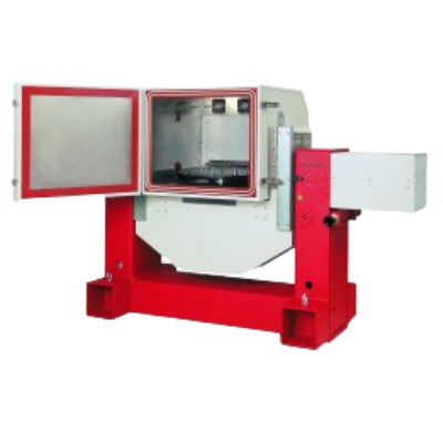
| Two Axis Motion Simulator | |
|---|---|
| Location resolution | 0,00001 ° |
| Location accuracy | <1 arcsec |
| Angular velocity resolution | 0,0001 °/s |
| Angular velocity stability |
±% 0.0002 < 400 °/s ±% 0.0005 < 1,000 °/s |
| Top speed |
1,000 °/s (internal axis) 400 °/s (outer axis) |
| Highest acceleration |
2,700 °/s² (internal axis) 260 °/s² (outer axis) |
| Max testable load | 40 kg |
| Temperature control | -60 to +90 °C |
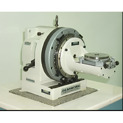
| Index Table | |
|---|---|
| Location accuracy | 0.25 arcsec |
| Repeatability | 0.05 arcsec |
| Location stability | 0.025 arcsec |
| Orthogonality | 2 arcsec |
| Location resolution | 1.0 deg |
| Loading limit | 10 lbs |
| Height x Width x Diameter | 2,620 x 1,755 x 1,219 mm |
| Weight | 310 lbs |
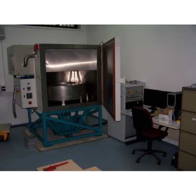
| Centrifuge Device | |
|---|---|
| Location resolution | 0,00001 ° |
| Location accuracy | <1 arcsec |
| Angular velocity resolution | 0,00001 °/s |
| Angular velocity stability | % 0,0001 |
| Maximum angular velocity | 4.000 °/s |
| Linear acceleration range | 0.5 - 200 g |
| Max testable load | 10 kg |
| Test chamber temperature range | -60 to +125 °C |
Rotameter Tests
Allan Variance Tests
These tests are performed by taking long term (hourly) data from stationary gauges. The different noise-induced errors are calculated from a graph based on the differences of the group averages of these meter data.
The calculated errors are:
- Quantization Noise
- Angle Random Walk
- Constant Shear Instability
- Long Duration Noise
These tests can be performed using three-axis motion simulator, two-axis motion simulator.
Calibration Tests
Each rotameter individually undergoes calibration tests. The calibration tests calculate the parameters of each rotameter. Calibration tests can be performed using a three-axis motion simulator or a two-axis motion simulator. During these tests, high precision rotational inputs are applied to the rotameter. These input values are based on the measurement range of the rotameter. As a result of the rotation tests, the coefficient of proportion, angle drift values and errors are calculated for the rotometers. By applying zero input, constant drift values are calculated. With these calculated coefficients, the calibration matrix of the gauges is created. This matrix is input to the AÖB or navigation software. After these tests, calibration tests can be repeated in detail at different temperatures. In this way, the change and repeatability of the parameters depending on the temperature are tested.
Test Specimen Specifications and Delivery Conditions
These tests can be applied to fiber optic, laser, pulsating and MEMs transducers. After selecting the appropriate device to test the rotometers to be tested, the appropriate test setup must be installed. This test rig consists of a mechanical interface for the placement of the transducer inside the device, an electrical interface and/or the necessary software to transfer the transducer data to the computer via sliprings or other means. After the necessary test setup is installed, a test plan suitable for the meter is prepared and measurements are made. The tests are reported in the Test Result Report.
Basic Devices Used in These Tests and Their Technical Specifications
| Two Axis Motion Simulator | |
|---|---|
| Location resolution | 0,00001 ° |
| Location accuracy | <1 arcsec |
| Angular velocity resolution | 0,0001 °/s |
| Angular velocity stability |
±% 0.0002 < 400 °/s ±% 0.0005 < 1,000 °/s |
| Top speed |
1,000 °/s (internal axis) 400 °/s (outer axis) |
| Highest acceleration |
2,700 °/s² (internal axis) 260 °/s² (outer axis) |
| Max testable load | 40 kg |
| Temperature control | -60 to +90 °C |
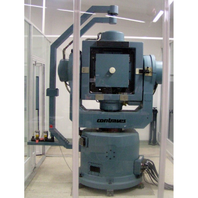
| Three Axis Motion Simulator | |
|---|---|
| Location resolution | 0,00001 ° |
| Location accuracy | <1 arcsec |
| Angular velocity resolution | 0,00001 °/s |
| Angular velocity stability | % 0,0001 |
| Highest Speed |
1,000 °/s (internal axis) 750 °/s (center axis) 500 °/s (outer axis) |
| Highest Acceleration |
1,660 °/s² (internal axis) 590 °/s² (center axis) 660 °/s² (outer axis) |
| Temperature Control | 55 to +85 °C |
Inertial Measurement Unit Tests
Today, Inertial Navigation Systems are used in civil and military navigation systems. In order to increase the performance of Inertial Navigation Systems, detailed tests of Inertial Measurement Units (IMU) should be performed. There are 3 accelerometers and rotometers in the ACU that measure acceleration and angular velocity information in 3 axes. For this reason, each gyrometer and accelerometer are tested separately. First, Allan Variance tests are performed to examine the overall performance of the meters. Then calibration tests are performed to calculate the parameters of each rotometer and accelerometer.
Allan Variance Tests
These tests are carried out by taking long-term data (in the order of hours) from stationary accelerometers and gyrometers. Different noise-induced errors are calculated from the graph drawn as a result of the process based on the differences of the group averages of these meter data. The calculated errors are as follows:
- Quantization noise
- Random Walk
- Constant Shear Instability
- Long Duration Noise
Calibration Tests
With these tests, error models are created for the gauges used in the MLC. Calibration tests are performed by applying high-precision acceleration and rotation inputs to the AÖB using a three- or two-axis motion simulator. Position tests result in constant drift, coefficient of proportion and angle drift values for accelerometers and constant drift values for rotometers. As a result of the rotation tests, the coefficients of proportion and angle shifts of the rotometers are calculated. With these calculated coefficients, a calibration matrix containing the parameters of the gauges is created. This matrix is input to the AÖB or navigation software. After these tests, calibration tests can be repeated in detail at different temperatures. In this way, the change and repeatability of the parameters depending on the temperature are tested.
Test Specimen Specifications and Delivery Conditions
After selecting the appropriate device to test the Inertial Measurement Unit to be tested, the appropriate test setup must be installed. This test setup includes the mechanical interface that will ensure the placement of the IMM in the device, the electrical interface and/or the necessary software to transfer the meter data to the computer via sliprings or other means. After the necessary test setup is installed, a test plan suitable for the meter is prepared and measurements are made. The tests are reported in the Test Result Report.
Basic Devices Used in These Tests and Their Technical Specifications
| Two Axis Motion Simulator | |
|---|---|
| Location resolution | 0,00001 ° |
| Location accuracy | <1 arcsec |
| Angular velocity resolution | 0,0001 °/s |
| Angular velocity stability |
±% 0.0002 < 400 °/s ±% 0.0005 < 1,000 °/s |
| Top speed |
1,000 °/s (internal axis) 400 °/s (outer axis) |
| Highest acceleration |
2,700 °/s² (internal axis) 260 °/s² (outer axis) |
| Max testable load | 40 kg |
| Temperature control | -60 to +90 °C |
| Index Table | |
|---|---|
| Location accuracy | 0.25 arcsec |
| Repeatability | 0.05 arcsec |
| Location stability | 0.025 arcsec |
| Orthogonality | 2 arcsec |
| Location resolution | 1.0 deg |
| Loading limit | 10 lbs |
| Height x Width x Diameter | 2,620 x 1,755 x 1,219 mm |
| Weight | 310 lbs |
| Three Axis Motion Simulator | |
|---|---|
| Location resolution | 0,00001 ° |
| Location accuracy | <1 arcsec |
| Angular velocity resolution | 0,00001 °/s |
| Angular velocity stability | % 0,0001 |
| Highest Speed |
1,000 °/s (internal axis) 750 °/s (center axis) 500 °/s (outer axis) |
| Highest Acceleration |
1,660 °/s² (internal axis) 590 °/s² (center axis) 660 °/s² (outer axis) |
| Temperature Control | 55 to +85 °C |


