FOR NATIONAL DEFENSE
NATIONAL R&D
AGENDA
News & Announcements
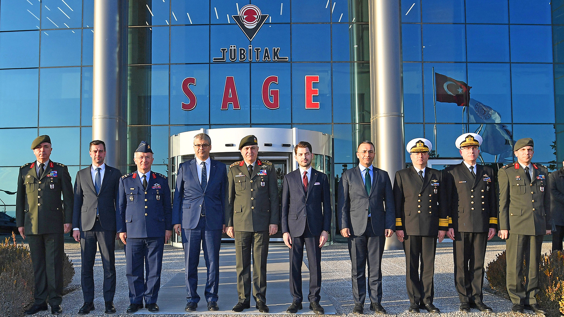
Chief of General Staff Org. Visit of Metin Gürak and his accompanying delegation to TÜBİTAK SAGE
Recruitment of 94 new personnel to be assigned at TÜBİTAK SAGE
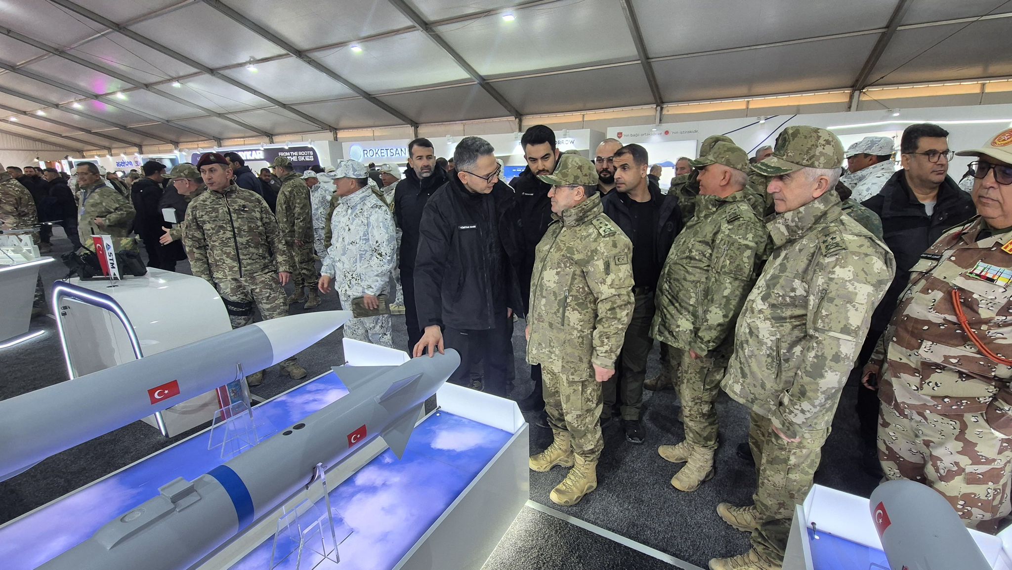
TÜBİTAK SAGE Winter Exercise-2025 Defense Industry Exhibition Participation
Job Announcement Drawing Results
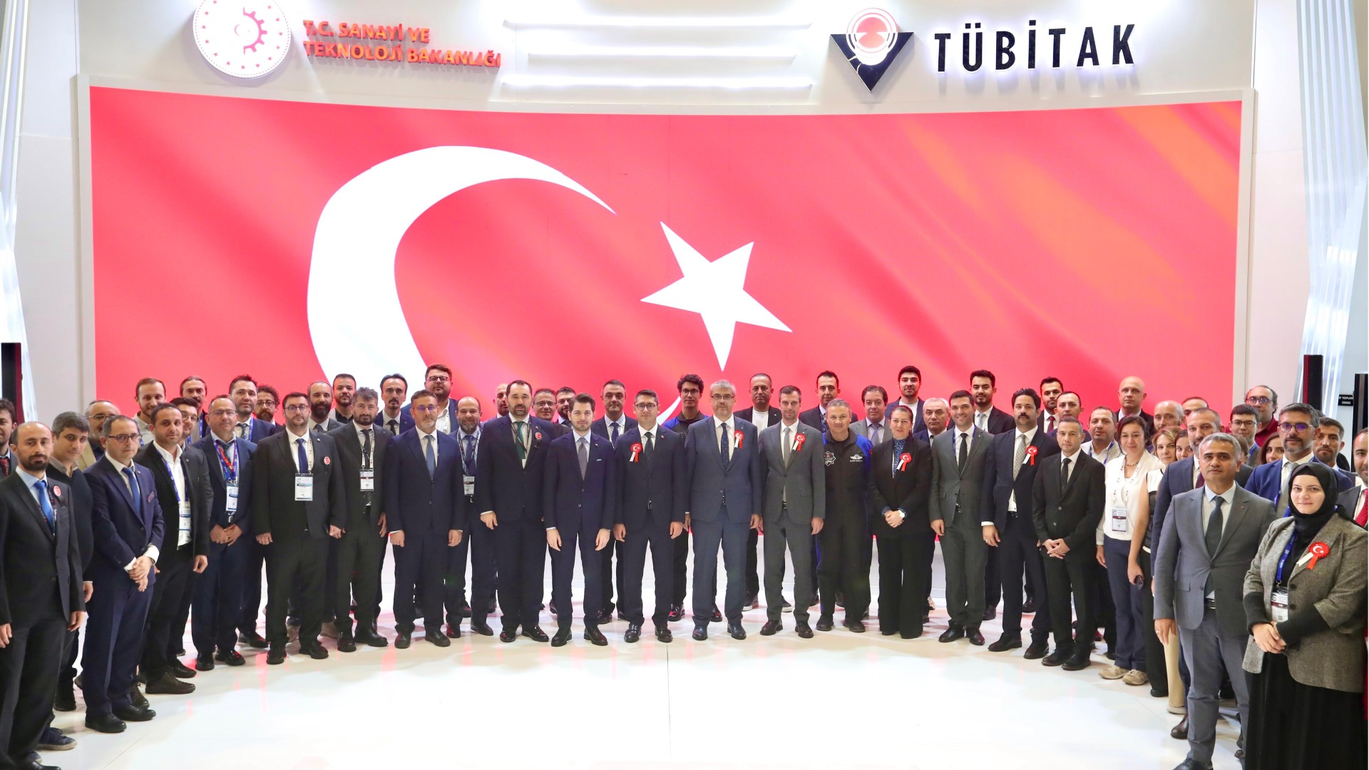
TÜBİTAK SAGE SAHA EXPO 2024 Participation
We took our place at TEKNOFEST 2024 as TÜBİTAK SAGE!
TUBITAK is Looking for Future Researchers!
Forklift Operator, Private Security and Protection Job Posting
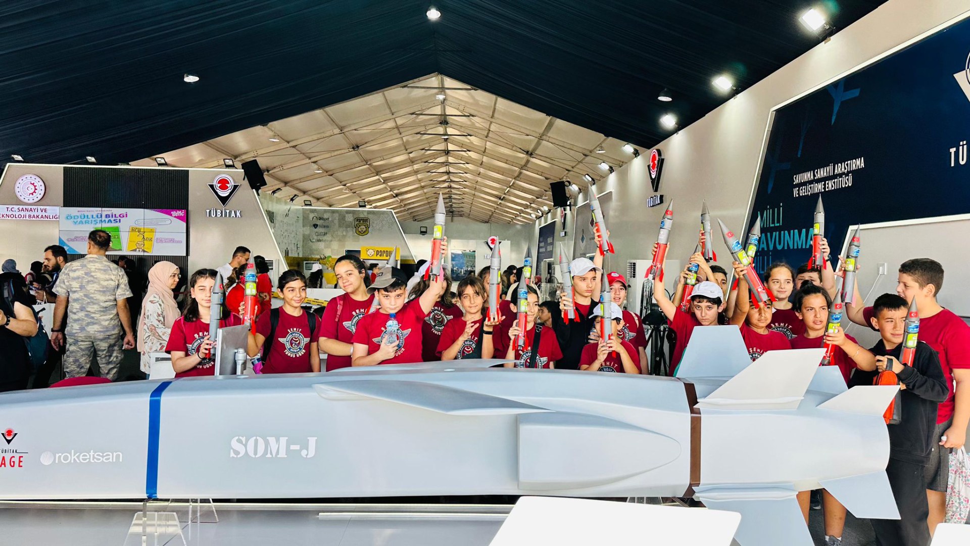
World's First and Only Vertical Landing Rocket Competition Ends!
Handover Ceremony at TÜBİTAK SAGE
ABOUT US
Who We Are
TÜBİTAK SAGE increases its know-how through research projects; designs and develops software and hardware through development projects; provides services through inspection, measurement and consultancy projects; and acquires the infrastructure required for the high quality products and services it aims to offer through infrastructure projects.
TÜBİTAK SAGE carries out projects with the Ministry of National Defense, Turkish Armed Forces, Presidency of Defense Industries and various defense industry organizations.
SAGE
Our Services
SAGE
Subsystems and Components
With us
Working
Investigate
Improve
Would you like one?
Do you want to
Work
Research
Develop
with us?
Frequently
Asked
Questions
TÜBİTAK Defense Industry Research and Development Institute (SAGE) carries out its activities with the aim of providing the Turkish Armed Forces and the defense industry with national technologies, products and services with high added value and competitiveness on a global scale through R&D.
The fields of activity and services provided by TÜBİTAK SAGE, which continues its activities in the defense industry, can be summarized as follows:
- In relation to guided and unguided munition systems/sub-systems;
- Conducting basic research activities,
- Conducting R&D projects,
- To carry out technology development studies,
- Building knowledge and specialized manpower,
- To realize the production (prototype production, low-scale initial production) of the developed strategic systems and subsystems,
- To carry out software development activities in the areas in which it is specialized (munition mission management, flight simulations, etc.),
- Providing test and measurement services,
- Developing and commissioning strategic infrastructures related to defense technologies,
- To provide technical support and consultancy services in its specialized fields.
TÜBİTAK SAGE continues its activities at its main campus in Ankara and has various infrastructure and offices in Eskişehir, Kocaeli, Muğla and Konya.
TÜBİTAK SAGE was established in 1972 and continues its activities with more than 50 years of experience and strong human resources.
Description. TÜBİTAK SAGE is a national R&D center, a public institution operating under TÜBİTAK and the Ministry of Industry and Technology of the Republic of Turkey.
In line with the needs of TÜBİTAK SAGE, "R&D Personnel, Expert Personnel, Technicians/Technicians, Service Personnel" are employed from different fields.
Employment varies according to the candidates' field of education within the framework of the position they want to work. The qualifications required for a position are clearly stated in the application conditions of the job advertisements published by TÜBİTAK SAGE.
Any Turkish citizen who is a citizen of the Republic of Turkey, has a clean criminal record, meets the foreign language requirements and meets the qualifications required for the position can work at TÜBİTAK SAGE.
Job postings published by our Headquarters, TÜBİTAK SAGE's corporate website www.sage.tubitak.gov.tr and social media accounts.
Job applications are made through the Job Application System on the corporate website of TÜBİTAK, kariyer.tubitak.gov.tr .
Internship applications are carried out centrally by the Presidential Human Resources Office and are made at the address kariyerkapisi.cbiko.gov.tr.
To receive services from TÜBİTAK SAGE, you can first review the details of the services that suit your needs on Our Services page. To apply for a service, you need to fill out the relevant application form on the Service Request page. Once your application is received, our expert team will evaluate it, and if deemed appropriate, a proposal will be sent to the applicant. After the proposal is confirmed in writing by the applicant, the necessary work will begin in coordination with the applicant.
For detailed information about the process, you can visit our Service Process page.
As one of Turkey's largest R&D centers, TÜBİTAK SAGE's technologies and products have transcended national borders. These indigenous and national technologies are being actively used by many countries (Europe, America, Asia and Africa, etc.) together with NATO within the framework permitted by our government.
Thanks to these efforts of our institution, our country has become a country that can export technology abroad in the field of defense industry and compete on a global scale.


