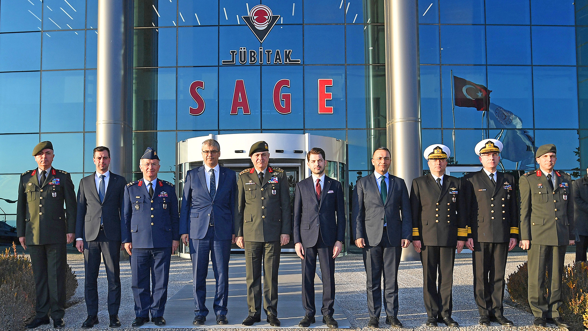
SAGE

Quality Control and Characterization Test Services

Quality Control and Characterization Test Request

To create a Quality Control and Characterization Test Request, please go to the relevant page and fill out the form.
Quality control and characterization tests are carried out to determine the physical, chemical, mechanical and functional properties of materials used for military and civilian purposes.

Non-Destructive Quality Control Laboratory

The Non-Destructive Quality Control Laboratory which was constructed at 2004, is a part of quality control division. Laboratory personnel (4 engineers and 2 technicians) are certificated according to EN ISO 9712. Radiographic inspection, ultrasonic inspection, magnetic particle testing, liquid penetrant testing and visual inspection systems available in non-destructive quality control laboratory, are described below.

Radiographic Inspection Capabilities

X-Ray System (Y. Access 100 X-Ray System)

Y. Access 100 X-Ray has 450 kV mini focus tube and 14 bit flat panel detector. The system is capable of moving in 4.5x9 m² space. The workbench was specially designed to meet all testing requirements. Samples have length of 8,000 mm and diameter of 1,000 mm can be inspected by using this x-ray system and the workbench.

X-Ray Tomography System (Y.CT Modular X-Ray System)

Y.CT Modular X-Ray System is used for 2-dimensional and 3-dimensional X-ray inspection (computed tomography) has 450 kV mini focus tube, 225 kV micro focus tube and 16 bit flat panel detector. Samples have length of 500 mm, diameter of 320 mm and weight of 50 kg can be inspected by using CT Modular system. The penetration depth of x-ray beam in a bulk steel is about 65 mm. Failure analysis, thickness analysis, geometric measurements and nominal/actual comparison is possible on 3-dimensionally inspected parts.

X-Ray Systems for Electronics

Y. Cougar SMT X-Ray System

Y.Cougar X-Ray System has 160 kV multi focus tube and 14 bit flat panel detector. It is used for 2-dimensional X-ray inspection of printed circuit boards (PCB’s) and electronic assemblies.

Y. Cheetah SMT X-Ray System

Y. Cheetah X-Ray System has 160 kV multi focus tube and 16 bit flat panel detector. It is used to inspect printed circuit boards (PCB’s) and electronic assemblies. Apart from the other x-ray system, computed laminography and computed tomography options are available.

Y. Cougar EVO X-Ray System

Y.Cougar X-Ray System has 160 kV multi focus tube and 14 bit flat panel detector. It is used to inspect printed circuit boards (PCB’s) and electronic assemblies. Computed tomography option is also available.

Comet Evo Portable X-Ray System

Comet Evo Portable X-Ray System has 160 kV multi focus tube and 16 bit flat panel detector. It is used for 2-dimensional X-ray inspection on field applications.

Ultrasonic Test Capabilities

Ultrasonic inspection is a bulk inspection technique which is preferred for the detection of internal imperfections that cannot be observed with radiography. Two conventional ultrasonic test equipment, (EPOCH 4PLUS, GE USM GO) and one phased array ultrasonic test equipment (Olympus OmniScan MX2) are available in non-destructive testing quality control laboratory.

Magnetic Particle Testing Capabilities

Magnetic Particle Testing Capabilities: Magnetic particle testing is used for the detection of surface/subsurface imperfections in ferromagnetic materials. Test can be performed under UV or visible light. For magnetic particle inspection, AC&DC hand yoke (AC 230V, 50Hz) and MP 2500 AC_FWDC Magnetic Particle Testing System are available in non-destructive testing quality control laboratory. Ferromagnetic samples have length of 2500 mm and diameter of 500 mm can be inspected by using MP 2500 AC_FWDC Magnetic Particle Testing System and surface/subsurface imperfections can be detected.

Liquid Penetrant Testing Capabilities

Discontinuties open to the surface of a material can be detected by liquid penetrant testing. The material surface should be clean and uncoated to allow the penetration of liquid dye into the discontinuties. Test can be performed under UV or visible light.

Visual Inspection Test Capabilities

Surface discontinuties are inspected by qualified personnel using visual inspection techniques. These techniques includes use of some lighting and measurement tools like torch, callipers, magnifying glass etc. For the visual inspection of non-reachable parts of the specimens, Videoscope Instrument has a fiber-optic cable with 6 mm diameter and 2 m length (GE Mentor Visual IQ VideoProbe) is used.

Materials Quality Control Laboratory

The successful employment of parts in defence applications relies on the ability of the raw materials to meet design and service requirements. The capability of a part to meet these requirements is determined by the physical, chemical and mechanical properties of the starting material using in manufacturing stage.

Mechanical properties, are described as the relationship between forces (or stresses) acting on a material and the resistance of the material to deformation (i.e., strains) and fracture. In Materials Quality Control Laboratory, different types of tests are used to determine properties, such as modulus of elasticity, yield strength, tensile strength, elastic and plastic deformation (i.e., elongation).

Tension/Compression Test Machine

Two identical Instron 5982 Dual Column Floor Model testing systems shown in Figure 1 is used in mechanical tests. A variety of load cells (1 kN, 10 kN, 100 kN) are available to provide accurate measurements for applications ranging from weak elastomers to those utilizing the full capacity of the load frame. Additionally, a full range of grips, fixtures, and strain measurement devices (Video extensometer and clip on extensometers) are also available.

Some important features of the device are given below:

  • 1 kN, 10 kN, 100 kN capacity load cells provide a wide range of test capability.
  • Environmental Cabinets can be used between -75°C and +180°C temperature interval.
  • 8 mm and 16 mm focal length Video Extensometer and 25/50 mm gauge length dynamic clip-on extensometer ensure high reliability and repeatibility on test result.

Dynamic Test (Fatigue) Instrument

Fatigue is a form of failure that occurs in structures under dynamic and cyclic stresses. (e.g., bridges, aircraft, and machine parts.) Normally, this type of failure occurs after a lengthy period of repeated stres sor strain cycling. It is catastrophic and insidious, occuring suddenly and without warning.

The Instron ElectroPuls E10000 (See Figure 4), used in the Materials Quality Control Laboratory, is an test instrument designed for dynamic and static testing on a wide range of materials and components. Some important features of the instrument is given below.

  • Oil-free linear motor technology for clean test conditions
  • Capable of operating at over 100 Hz
  • ±10 kN dynamic linear load capacity and ±100 Nm dynamic torque capacity

Air Conditioning Cabin

Conditioning of the test specimens in accordance with desired test procedures is made by climatic and thermostatic chambers. In the laboratory there are four different types of chambers. Three of them are integrated to the universal testing machines and one is used independently. Temperature range of chambers are up to -75 °C for cooling and +180 °C for heating.

Rockwell Hardness Tester

One of the characteristic test conducted on metallic materials (especially in heat treated parts) is Rockwell Hardness Test. The Rockwell hardness test can provide useful information about metallic materials. This information may correlate to tensile strength, wear resistance, ductility, and other physical characteristics of metallic materials, and may be useful in quality control and selection of materials.

Shore Hardness Tester (Durometer)

Durometer is an instrument that is widely used to determine the hardness of many organic materials like soft rubber, elastomers,natural rubber products,neoprene, casting resin,polyester, soft PVC, leather, etc. Hardness measurements can be carried out easily in various methods (A, B, C, D, DO, E, M, O, OO, OOO, OOO-S, R) by changing applied force and the indenter type of the durometer.

Optical Emission Spectrometer

The chemical composition requirements is determined by the Optical Emission Spectrometer with Argon flushed spark stand for quantitative spectrochemical analysis of metal samples. As with all emission phenomena, optical emission involves the expulsion of photons as electrons in excited states drop back to lower states. In the case of optical emission, the process involves the excitation or ejection of outer shell (or valence) electrons. The line spectra produced by these electron transitions are characteristic of the element involved.

X-Ray Fluorescence (XRF) Analyzer

X-Ray Fluorescence is defined as secondary X-rays from a material that has been excited by bombarding with high-energy X-rays. When high energy photons are emitted from an X-rays source to a substance, they are absorbed by atoms and inner shell electrons are ejected from the atom. This leaves the atom in an excited state, with a vacancy in the inner shell. Outer shell electrons then fall into the vacancy, emitting photons with energy equal to the energy difference between the two states. Since each element has a unique set of energy levels, each element emits a pattern of X-rays characteristic of the element, termed “characteristic X-rays”. By analyzing intensity of characteristic X-rays, the chemical composition of any material can be can be calculated. The phenomenon is widely used for analysis of elements starting from sodium to uranium in the periodic table.

Conductivity Meter

Electrical conductivity is a distinctive material property. Conductivity meter made with eddy current technique is a method used to determine the heat treatment status of non-ferrous metals and especially aluminum alloys. The unit of conductivity is Megasiemens/meter (MS/m), and the measurement unit used in direct reading measuring devices is generally given as IACS.

Dimensional Quality Control Laboratory

In the Dimensional Quality Control Laboratory, dimensional quality control activities are carried out for the parts and components produced within the scope of projects, from raw material to the finished end product. Especially for precise measurements, dimensional quality control activities are carried out in a controlled laboratory environment.

Within the scope of dimensional quality control, complex parts are measured with CMM (Coordinate Measuring Machine), optical scanning and profile projection devices. In addition, ultrasonic thickness, coating and paint thickness measurements, surface roughness measurements, thread checks and measurements are performed with conventional quality control devices.

Geometric and Form Measurements

The form characteristics of the products assembled together are of utmost importance. Form error is defined as the deviation of the shape of the product from the relevant geometric shape.

Circularity and Form Measurement Capabilities

  • Form measurements can be made at the following accuracies:
    • Circularity Uncertainty: (0.02 + 0.0005) µm
    • Cylindricity Uncertainty: 0.15 µm (at 100 mm)
    • Sensitivity to runout, coaxiality, perpendicularity, parallelism (at 100 mm): 0.4 µm
  • Measuring Part Limitations:
    • Part Length (Maximum): 470 mm
    • Part Weight (Maximum): 60 kg
    • Inside Diameter (Maximum): Ø364 mm
    • Outer Diameter (Maximum): Ø280 mm

Form Contour Measurement Capabilities

It is mainly used for industrial applications and is used to determine the dimensions, shapes and geometric details of objects. Measurement can be made with an uncertainty of ±(0.25 + H/250) µm for radius, chamfer, step etc. forms larger than 0.05 mm:

  • Part Length (Minimum): 0.01 mm
  • Part Length (Maximum): 140 mm
  • Part Weight (Maximum): 90 kg
  • Inner Diameter Scan Length: Minimum Ø3 mm

Precise Dimension Measurement Capabilities

Measurement Capacities
  • High Precision Dimensional Measurements
    • Measurement can be made with an uncertainty of ±0.09 L / 2000 µm in inner and outer diameters.
    • Outside diameter measurement capacity: 0 to 300 mm
    • Inner diameter measurement capacity: 5 to 150 mm
    • Part weight (maximum): 11 kg
Coordinate Measurement System
  • Measurement According to Cartesian Coordinate
    • The head of the system, which moves in X, Y and Z axis, rotates 360 degrees on its own axis and offers versatile measurement.
    • Software used: Camio and PC-DMIS
    • Technical competencies and capabilities such as technical training, part program software, program accuracy checks are available.
Device Measurement
  • Uncertainty: 0.5 + L/500 µm (Minimum)
  • Measurement Capacities on Different Axes
    • X axis 700 mm (minimum), 1500 mm (maximum)
    • Y axis 1000 mm (minimum), 3300 mm (maximum)
    • Z axis: 650 mm (minimum), 1350 mm (maximum)
  • Device Measurement Volume
    • 700x1000x700 mm and 900x1500x800 mm
Software and Components
  • Software Used
    • Pc-Dmis CAD++
    • GOM Inspect Professional
    • Geomagic Control X
  • Components Required for Dimensional Measurement Studies
    • Components such as probes, extensions, apparatus are available in the infrastructure.
Laboratory Equipment and Systems
  • Dimensional Quality Control Laboratory
    • ATOS II, AICON Smart Scan, Breuckmann OPTO-TOP optical scanning systems
    • AICON DPI Pro (Photogrammetry) system
Surface Roughness and Physical Properties
  • Surface Roughness
    • Output is provided at the value of all surface parameters (Ra, Rq, Ry, Rz, etc.).
    • Measurement range: ±250 µm (up to ±750 µm with 3 x probe arm length)
    • Profile resolution:
      • Measuring range ± 250 µm: 8 nm
      • Measuring range ± 25 µm: 0.8 nm
      • Measuring range ± 500 µm: 16 nm
  • Inside Diameter Profile Surface Measurement Capacity
    • Min Ø25 mm diameter up to 125 mm depth
    • Min Ø5 mm diameter up to 75 mm depth
Measuring Instruments Used
  • Surface Roughness Measuring Instrument
    • MITUTOYO surface roughness measuring instrument
  • Ultrasonic Thickness Gauge
    • OLYMPUS ultrasonic thickness gauge
  • Traditional Quality Control Devices
    • Requested dimensional measurements can be made.

Chemical Quality Control Laboratory

The Chemical Quality Control Laboratory, which is a part of quality control group, meets the characterization and quality control requirements of propellants, pyrotecnics, explosives and other different types of chemicals such as polymers, composites and insulation materials.

Studies are carried out in the Chemical Quality Control Laboratory with 2 researchers and 3 technicians. Information about the devices in our laboratory and the studies carried out with these devices are given below. Detailed information about the devices is also given in a table. Information about the analyzes performed other than instrumental analyzes is also given in a separate table.

Dynamic Mechanical Analysis (DMA)

DMA is a device used to determine the mechanical properties of materials by changing their temperature and frequency characteristics. It works with materials such as films, solid polymers, foams and composites. The DMA device is used to determine the glass transition temperature (Tg) and to study the viscoelastic properties of materials with appropriate apparatus (clamps). Single-dual cantilever, single-dual cantilever, 3-point bending, compression, tensile and film heads are often used with the DMA machine. Available clamps are also included in the specifications of the device. Time-temperature superposition (TTS) analyses are also performed with the DMA device. With these analyzes, aging/life information about materials is obtained.

Situations where TTS work cannot be carried out are as follows:

  • Samples with crystalline structure. Cases of partial melting in the temperature range to be studied.
  • Changes in the structure of the sample with temperature.
  • The sample is a block copolymer.
  • The sample is composed of polymers with different structures.
  • Different viscoelastic mechanisms other than configurational changes in the polymer (such as side-group movements).

High Performance Liquid Chromatography (HPLC) Analysis

High Performance Liquid Chromatography (HPLC) is a qualitative and quantitative technique for determination of chemical constituents. There should be reference calibration materials, appropriate columns and dedectors for analytes.

Thermal Analysis

Dynamic Mechanical Analyzer (DMA)

DMA is used to analyze the mechanical properties of a material by changing temperature and frequency. Materials such as films, solid polymers, foams and composites can be tested in DMA. Glass transition temperatures (Tg) can be detected and viscoelastic properties of materials can be studied by using appropriate clamps. Aging information of materials can also be obtained from DMA studies by time-temperature superposition experiments (TTS). Exceptional cases are given below:

  • Glass Transition Temperature (Tg): The temperature at which the material transitions to the glassy state.
  • Melting Temperature (Tm): Melting temperature of the material.
  • Crystallization Temperature (Tc): The temperature at which the material transitions to the crystalline state.
  • Decomposition Temperature (Td): The temperature at which the material starts to degrade.
  • Thermal Stability and Oxidation Stability: Thermal and oxidative resistance properties of the material.
  • Heat Capacity (Cp): Thermal capacity of the material.
  • Curing Time: Curing time of the material.

Analyzes are performed in nitrogen, argon or oxygen environment. Before the study, the decomposition temperature of the sample is determined in the thermogravimetric analyzer and the analysis is carried out in a way to stay below this temperature. Considering the behavior of the sample during and after combustion and the damage it may cause to the device chamber and the device, it is determined whether DSC analysis can be performed.

Thermogravimetric Analysis (TGA) Device

Thermogravimetric Analysis (TGA) is used to study the weight changes of materials against temperature. This device works by holding the materials at a certain temperature for a certain period of time or by heating-cooling at different scan rates to determine the weight changes and decomposition temperatures of the materials. Depending on the model of the TGA instrument, the operating range can be selected between room temperature and 1,000°C or 1,500°C.

During these analyzes, different ambient gases (oxygen, nitrogen, argon, etc.) can be used according to the analysis needs. By using kinetic models suitable for the material, the desired kinetic calculations and aging profiles can be obtained. It can be analyzed whether two or three materials are compatible with each other.

The Chemical Quality Control Laboratory has two TGA devices, one with a vertical oven (RT-1,000°C) and one with a horizontal oven (RT-1,500°C). Differential Thermal Analysis (DTA) can also be performed simultaneously with the horizontal oven device.

FTIR Analyzer

Fourier Transform Infrared Spectrometry (FTIR) is used to obtain information about the chemical bonding of materials. This device is used in analyses such as molecular bond characterization of materials, detection of functional groups, material comparisons, the state of bonds in the material structure and the detection of structural differences. The FTIR device in our laboratory operates in the 400-4,000 cm-1 range and has diamond-ATR (Attenuated Total Reflectance) and Ge-ATR modules. Thanks to these modules, FTIR analysis of materials can be performed directly without the need for KBr pellets.

Moisture Analysis

A reference method, Karl Fischer titration, is used to determine the moisture content of materials. Moisture analysis can be performed titrimetrically (volumetrically) for materials with high water content (% 5 and above) and coulometrically for materials containing less than one part per million (ppm) moisture (1 ppm - % 5). In addition, moisture analysis of solid materials can be performed quickly with an autosampler and an oven unit that can reach up to 280 °C.

Density Measurements

In our laboratory, true density measurements of solid and gel materials that will not damage the sample container are performed using a helium pycnometer. In addition, tap density and bulk density measurements are also performed for powdered materials. Images of the related devices are given below.

Stojan Vessel Burning Rate Tester**

Stojan Vessel Combustion Rate Tester is a device used to determine the combustion rates of solid fuels. Unlike devices working with the Strand burner principle, it allows the calculation of combustion rates between 0-500 bar by collecting data at all pressure values against time for fuels conditioned at a certain temperature. The SV combustion rate device can also be used as a closed bomb to measure the pressure value during combustion between 0-500 bar.

Test specimens are conditioned and tested between -70 and +180°C. For specimens conditioned below room temperature, X-ray analysis is also requested and if no deformation is observed after this analysis, the test is continued. For occupational safety reasons, it is mandatory to provide detailed information about the properties of the test samples before the test application and to make an assessment by our infrastructure on whether it is safe to work with the SV device. After this evaluation, the test procedures will be started. It will be the responsibility of the company requesting the test to cover any damage caused by the sample during the test.

The desired test dimensions of solid fuel samples are given below:

  • The thickness (e0) of the disk type specimen should be 10 mm ± 5 mm and the length should be 60 mm ± 20 mm.
  • The thickness (e0) of the tube type specimen should be 10 mm ± 5 mm, diameter 30 mm ± 10 mm and length < 10x (diameter-2x thickness).

Calorific Value Tester (Oxygen Bomb)

Calorific Value Tester is a device used to determine the amount of energy released by the combustion of energetic materials. This calorimeter is electrically ignited in a water chamber containing pure water of constant weight and temperature in a closed bomb system, causing the sample to burn. The energy released at the end of combustion is measured in cal/g or j/g and this value is determined at the end of the test.

Tests are usually carried out in nitrogen, argon or oxygen. For tests to be carried out in an oxygen environment, a preliminary assessment by the laboratory in terms of occupational safety is mandatory. This assessment is important to ensure that the tests are carried out safely.

Impact Sensitivity Test

The impact sensitivity test is performed to determine the response of energetic materials to impact. The BAM (Bundesanstalt für Materialforschung und -prüfung) method is applied in this test. The test examines whether the material reacts, degrades or explodes. The application procedure of the test is as follows:

  • Specified weights (1, 2 and 5 kg) are dropped on the sample from a specified standard height (maximum 100 cm).
  • The reaction of the specimen is observed. The specimen is considered to be degraded if flame or smoke is observed, or if ash deposits are observed on the impact test apparatus when the top cylinder is removed.
  • According to the method applied, if a positive reaction is seen in one of 6 shots (1/6 method) or the energy point where the energetic material reacts positively with a probability of % 50 is reported as the test result.

Friction Sensitivity Test

The friction sensitivity test is performed to determine the sensitivity of energetic materials to friction. The BAM (Bundesanstalt für Materialforschung und -prüfung) method is used for this test. As a result of the test, it is examined whether the material reacts, degrades or bursts. The application procedure of the test is as follows:

  • Any change in the color and odor of the tested material is considered as degradation.
  • A spark, flame, smoke or crackling heard during the test is considered a positive reaction.
  • Depending on the method applied, a positive reaction in one of 6 trials (1/6 method) or the energy point at which the energetic material reacts positively with a probability of % 50 is reported as the test result.

Thermal Conductivity Coefficient Determination Device

This device is capable of determining the thermal conductivity coefficients of polymer, foam or ceramic materials in the temperature range from -70 to +180°C. The sample size must be at least 5 mm thick and 2.5 cm in diameter for the measurement.

UV-VIS Spectrophotometer

The UV-VIS spectrophotometer is an analytical device that provides qualitative and quantitative results operating in the ultraviolet and visible regions. In UV-VIS regions, it determines the content by absorption of light by molecules. A calibration curve is needed for content determination.

Viscosity Device

The kinematic viscosity device measures how fast fluids move under gravity.

Electronic Quality Control Laboratory

The Electronics Quality Control Laboratory is staffed by 3 engineers and 5 technicians. The infrastructure of the laboratory is capable of performing various quality control inspection methods such as quality control of printed circuit boards, components and soldering workmanship, wiring tests, acrylic coating controls and electrostatic discharge tests before and after typesetting. Below is information about the devices used in these methods and their capacities.

Solder Fill and Component Damage Inspection

After checking the presence/absence of components and the accuracy of directional information, solder fill and component damage are visually inspected according to the Class 3 requirements of the IPC-610 standard. Tools and systems such as table top magnifier, stereo microscope, HD high resolution camera and AOI (Optical Inspection Instrument) are used for visual inspection.

Stereo Microscope

The Electronic Quality Control Infrastructure has 3 different microscope types, with magnification capacities of "40X", "90X" and "200X". The "90X" magnification microscope has the ability to rotate the image 360° around its axis and to view the image at a 360° angle from the top.

AOI (Optical Inspection Instrument)

In order to perform inspection with the AOI device, the schematic of the board must be created using gerber data information and the program must be written. After the schematic information of the board is defined to the device, inspection criteria such as dimensional properties, solder filling, directional information are defined one by one according to the types of electronic components. The defined information and program are saved in the device's database and when the same type of board is inspected, the relevant program can be used to perform the inspection quickly. The inspection capabilities of the AOI device are as follows:

-         Detectable Component Fault Types: It is capable of detecting defect types such as missing, offset, skewed, misaligned, planted, upturned, inverted, incorrect, damaged components.

-         Solder Failure Types: For cream solder, wave solder or hand soldering, it is capable of detecting defect types such as short circuit, capillary short circuit, unsoldered, under or over soldered, partial soldering, improper solder balls.

In order to perform a card inspection with the AOI device, the card must either come with a panel or there must be a distance of at least 5 mm from the edge of the card to the nearest component pad.

Technical Specifications:

  • Sample Size: 508 mm x 508 mm PCB (max)
  • Resolution: "40 fps for 8.3 Fm/pixel resolution in high-resolution mode"
  • 0.5 µm resolution along the Z direction
  • Measurement Method: "Fringe projector for 3D analyses"

Conformal Coating Visual Inspection Principles

Conformal coating is applied to protect the electronic card equipment whose electrical tests have been completed from environmental conditions. During the quality control of the applied conformal coating, the homogeneity of the coating under violet light, air bubbles, fluctuations and the presence or absence of acrylic coating where necessary are checked.

Quality Control Principles of Cabling

Electrical testing and visual inspection of the completed cabling is carried out according to the Class 3 criteria of the IPC-620 standard and the requirements in the relevant source document.

 The following functions can be performed in the electrical test step:

  • Conductivity test
  • Short circuit
  • Insulation
  • HiPot tests

For electrical tests, tests are carried out with a device with 32 port inputs and a voltage of 1,500 VDC.

In order to apply RF testing to antenna cabling, there is a Network analyzer device that can measure between 100 kHz-8 GHz. With this device, features such as VSWR and signal loss are analyzed.

In the visual inspection step, features of the cabling such as connector damage, pin damage, tubing/cable sheath damage, cable exit direction of the connector are checked.

Electrostatic Discharge Test

Electrostatic Discharge (ESB) Device: 330/500/5.000/5.000 MOhm, 2kV-25kV test voltage range. It can be operated with computer or manually with "Air" and "Contact" with positive and negative "discharge" capacity.
Search